Rebar Stirrups Calculator: Count, Cut Length & Spacing
Perimeter to hooks, hooks to cut length, cut length to count, count to pounds on the order sheet. Set the beam below and watch every stirrup number re-derive itself — including the +1 the fence-post rule owes you.
Stirrup Calculator — dial the beam, read the cage
Defaults model the everyday 12×24 in beam: #3 closed stirrups at 6 in with 135° seismic hooks. Densified end zones and the d/2 spacing cap live in the guide below — this tool runs the uniform-spacing base case.
Cross ties appear when legs exceed 2: (legs/2 − 1) per station, each spanning the depth minus cover plus its own pair of hooks. Count carries the fence-post +1 so both ends of the span close. Order weight adds 10% for laps of cross ties, tying scraps, and the pieces the crew bends twice.
Stirrups are the smallest bars on the job and the ones that decide whether a beam stands up after the concrete cracks. They are also the most under-ordered item in residential and light-commercial rebar — not because the math is hard, but because three separate numbers get confused: the cut length of one stirrup, the count over the span, and the weight on the order sheet. This page runs all three from a single formula chain, with a live calculator for the arithmetic and a worked 12×24 in beam that reproduces every default on the dashboard above.
The 12×24 in Beam Worked Example: 41 Stirrups From One Formula
Set the calculator to its defaults — b = 12 in, h = 24 in, 20 ft clear span, 1.5 in cover, #3 stirrups at 6 in, 135° hooks, 2 legs — and walk the chain. Five short steps take you from bare dimensions to a delivery ticket, and every intermediate number is visible on the dashboard when the sliders sit at their starting positions.
Outside perimeterGeometry
Cover 1.5 in per face leaves an inside-out rectangle of 12 − 3 = 9 in wide and 24 − 3 = 21 in deep. Perimeter = 2×9 + 2×21 = 60 in. This is the concrete-contact length the stirrup must wrap — everything else is hooks.
Hook extensionsFabrication
A 135° seismic hook carries a 10d straight extension: 10 × 0.375 = 3.75 in per hook on a #3 bar, and a closed stirrup has two hooks — 7.5 in total. Skip this step and every cage on the job comes up 11% short.
Cut length per stirrup
60 + 7.5 = 67.5 in, or 5.63 ft. With two legs there are no cross ties; a 4-leg cage on the same beam would add one 28.5 in tie per station and land at 96 in — the multi-leg section below works that variant.
Count over the span
n = ceil((240 − 3) / 6) + 1 = ceil(39.5) + 1 = 41 stirrups. The ceiling rounds the 39.5 spaces up to 40, and the +1 is the fence-post rule: 40 spaces need 41 posts to close both ends of the beam.
Weight and the order sheet
41 × 67.5 ÷ 12 = 230.6 ft of #3, and 230.6 × 0.376 lb/ft = 86.7 lb net. Add 10% for tying scraps and re-bends and the order reads ≈ 95 lb — one bundle off the fabricator's rack.
What Stirrups Actually Do (and Stirrups vs Ties)
A loaded beam wants to fail along a diagonal: near the supports, cracks open at roughly 45° and race from the bottom fiber toward the top, and the longitudinal steel running horizontally can do nothing to stop them. Stirrups are the answer — vertical legs laid across the crack's path, engineered to catch the diagonal tension the concrete sheds after it cracks. The capacity they add is Vs = Av × fy × d / s: shear steel area times yield strength times effective depth, divided by spacing. Run the 12×24 example: a two-leg #3 stirrup offers Av = 0.22 sq in (0.11 per leg), fy = 60,000 psi, d ≈ 21.5 in, s = 6 in — Vs = 0.22 × 60,000 × 21.5 / 6 ≈ 47,300 lb. Every 6 inches of beam buys about 47 kips of shear capacity, which is why halving the spacing doubles the shear steel while adding only 41% more bars: the number that matters is steel per inch, not steel per piece.
Ties look identical and do a different job. In a column, the verticals carry the load and the ties exist to confine the concrete core — holding it together under compression so it keeps gaining strength as it tries to dilate — and to keep the big vertical bars from buckling outward between floors. In a beam, the stirrup is a tension member crossing a diagonal crack. Same bend, opposite stress path: the stirrup works in tension across shear, the tie works in confinement around compression. The full shear-side derivation lives in our rebar shear strength guide, and the longitudinal bars the stirrups wrap — tension, compression, and hanger steel together — are laid out beam-by-beam in how to calculate rebar in a beam. That beam guide covers all the beam steel; this page stays deliberately narrow on the stirrups themselves.
Two-Leg, Four-Leg, Six-Leg: When One Loop Stops Being Enough
A single closed loop gives a beam two vertical legs — one on each face. Shear demand scales with member size, and past roughly 24 inches of depth a single loop's legs either crowd the spacing cap or fall short of the steel area the shear check wants. The fix is not a bigger bar first; it is more legs: an extra cross tie per added leg-pair, splitting the section so more vertical legs cross the diagonal crack.
| Legs | Typical member | Added cross ties | Per-station length change |
|---|---|---|---|
| 2-leg | Beams up to ~24 in deep — the everyday floor framing case | None — the closed loop is the whole stirrup | Base: 67.5 in per station on the 12×24 example |
| 4-leg | Deep beams and girders over ~24 in, or heavy concentrated shear | 1 cross tie per station (legs/2 − 1) | +28.5 in → 96 in per station on the 12×24 example |
| 6-leg | Wide transfer and collector beams with 3+ longitudinal layers | 2 cross ties per station (legs/2 − 1) | +57 in → 124.5 in per station on the 12×24 example |
Watch the 4-leg math on the 12×24 example. Each cross tie spans the depth at (h − 2c) = 21 in, plus its own pair of 3.75 in hooks — 21 + 7.5 = 28.5 in per tie. A 4-leg station is the closed 67.5 in loop plus one tie: 96 in per station. The count stays 41 — spacing is governed by the same formula — but total bar length jumps from 230.6 ft to 41 × 96 ÷ 12 = 328 ft, and weight from 86.7 lb to 123 lb. That is a 42% steel increase for one added tie per station, which is exactly why multi-leg cages are a designer's decision rather than a field upgrade: the shear check must ask for the legs before the crew bends them.
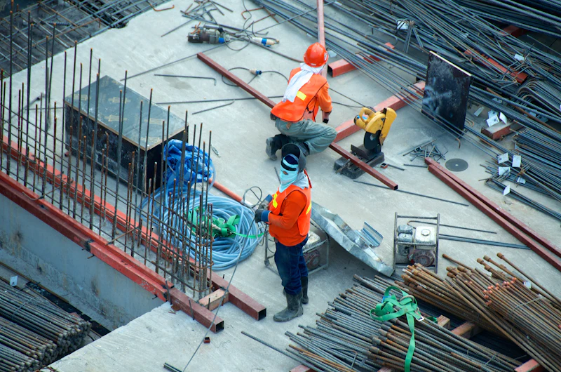
Tied in the Air, Checked on the Ground
Stirrups are the first thing an inspector counts and the last thing a crew wants to add after the pour. Every piece on this page's order sheet — the 41 loops, the hooks, the cross ties — gets tied around the longitudinal bars while the cage is still accessible, which is why the count formula rounds up and the cut length carries the hooks: a stirrup discovered missing on pour morning cannot be inserted, only drilled and epoxied at ten times the price.
The Cut Length Formula: Perimeter Plus 135° Hook Extensions
Every stirrup cut length is one rectangle plus two hooks. The rectangle is the outside perimeter measured to the stirrup's own centerline: the member dimensions minus twice the cover on each axis — 2×(b − 2c) + 2×(h − 2c). On the 12×24 beam that is 2×9 + 2×21 = 60 in. Notice what the formula does not include: bend curvature corrections are inside the fabricator's chart values, so the field formula stays two subtractions and a doubling — phone arithmetic, no software required.
The hooks are where cut lists go wrong. The 135° seismic hook — the default on this page and the standard for beam stirrups in any seismic jurisdiction — carries a straight extension of 10d past the bend: 3.75 in on a #3, 5 in on a #4. That is a fabricator chart value, and it conservatively covers the ACI code minimum for a seismic hook, which is the larger of 6d and 3 in (5.0 in for the #3 against a 3.75-in chart value — the chart governs because fabrication consistency, not the minimum, is the goal). The two hooks add 7.5 in on the example, taking 60 in of perimeter to a 67.5 in cut.
The other bends follow the same chart logic with different extensions: a 90° hook uses 12d (4.5 in on a #3) because the shorter wrap anchors less efficiently and needs more straight tail, while a 180° hook uses max(4d, 2.5 in) — 2.5 in on both #3 and #4 — because the full semicircular wrap does the anchoring work itself. Switch the hook dropdown in the calculator and watch the cut length move: 135° gives 67.5 in, 90° gives 69 in, 180° gives 65 in on the same beam. Three inches of steel per piece is the entire cost of seismic compliance on a stirrup, which is why nobody value-engineers the hook type — the engineer specifies it, and the fabricator bends it.
How Many Stirrups: The Spacing Formula and Densified End Zones
The count formula is n = ceil((clear span − 2×cover) / s) + 1, and each piece of it earns its place. The span converts to inches and loses the cover at each end because the first and last stirrups sit inside the cover, not at the raw beam face. The ceiling function rounds up because a partial space still needs a full stirrup. And the +1 is the fence-post effect: a 20 ft run at 6 in spacing creates 39.5 spaces, which round to 40 — and 40 spaces require 41 posts to close both ends. Forget the +1 and every beam on the job is one stirrup short at the support, which is where shear peaks.
Real details rarely run uniform spacing, because shear does not distribute uniformly either — it peaks at the supports and falls toward midspan. The standard answer is densified end zones: half-spacing over roughly the first 2h from each support face, full spacing through the middle. Walk the 12×24 example with h = 24 in and s = 6 in:
- First stirrup: at s/2 = 3 in from each support face — not at 6 in — so the critical zone right where the diagonal crack starts is caught early.
- Each densified zone: the first 2h = 48 in of beam, stirrups every 3 in from 3 to 48 → 16 pieces per end, 32 total.
- Mid-zone: the remaining 240 − 96 = 144 in at 6 in → 24 pieces between the zones.
- Recount: 32 + 24 + the fence-post close-out = ≈ 57 stirrups against the 41-piece uniform count — about 16 extra pieces, or roughly 30 lb of #3 on this beam, for a layout that actually matches where the shear lives.
The calculator runs the uniform base case so the arithmetic stays reproducible; when a drawing shows zones, count each zone separately with the same ceil-then-add-one rule and sum them. What never changes between layouts is the spacing cap: ordinary beams hold s ≤ d/2 and ≤ 24 in, so the 24-inch-deep example caps at about 10.75 in no matter how generous the shear numbers look.
Beam Stirrups vs Column Ties: Same Bend, Different Rules
Hand a crew foreman a stirrup and a column tie and he will see the same bent #3. Hand the code the same two bars and it writes different spacing limits, different densified zones, and different hook rules for each. The matrix below keeps the two straight.
| Aspect | Beam stirrups | Column ties |
|---|---|---|
| Primary job | Resist diagonal tension — carry the shear the concrete cannot between cracks | Confine the concrete core and hold verticals straight against buckling |
| Spacing cap (simplified) | d/2 and ≤ 24 in for the everyday shear case — tighter where shear demand controls | Smallest of 16 × vertical bar diameter, 48 × tie diameter, least column dimension |
| Densified zones | Ends: first ~2h from each support face at half spacing (or s/2 to the first stirrup) | Joints: over the depth of the connection above and below slabs, at half spacing |
| Hook direction | 135° hooks alternate end-for-end station to station so the core stays symmetric | 135° hooks alternate corners; every other tie flips the hook pair |
| Multi-leg growth | Cross ties split the section — 4-leg = loop + 1 tie, 6-leg = loop + 2 ties | Rarely needed below huge columns; ties stay single-loop even at 36 in |
Read the spacing-cap row as the practical difference: a beam's stirrup spacing is a shear-capacity dial that the designer turns down toward the supports, while a column's tie spacing is mostly a proportion rule — 16 times the vertical bar diameter, 48 times the tie diameter, or the least column dimension, whichever is smallest — tightened only where the joints demand confinement. On a 24 in column with #8 verticals and #3 ties, that cap is the smallest of 16×1.0 = 16 in, 48×0.375 = 18 in, and 24 in → 16 in. The same member in a seismic joint zone tightens to roughly half that. Hooping — wrapping the whole joint region in closely spaced confinement — is the extreme case, and it is detailed on the drawing, never improvised.
Choosing the Stirrup Diameter: The #3 Floor and the #4 Ceiling
Two sizes cover virtually every cast-in-place stirrup in buildings, and the choice is less about shear math than the industry pretends. #3 is the floor: the minimum stirrup for common beams everywhere, cheap (0.376 lb/ft), easy to bend to tight 135° radii, and adequate for the shear demand of anything up to a moderately loaded 24-inch beam at normal spacing. When a #3 at the d/2 cap cannot supply the required Av, the first move is usually more legs, not a fatter bar.
#4 is the ceiling, and three conditions push a detail up to it. Depth: beams deeper than about 24 in want the stiffer bar to hold shape over the longer legs — a 6 ft #3 leg is a noodle before the pour. Longitudinal load: beams carrying #10 and #11 bottom bars need ties stiff enough to keep those bars straight against buckling, and a #3 will bow where a #4 holds. Shear density: when the required Av exceeds what 2-leg #3s at 3 in can deliver, #4 legs at wider spacing carry the same steel with fewer pieces to tie. What has no place in the conversation is anything below #3 — a #2 stirrup has no standard hook geometry, cannot be bent reliably at seismic radii, and appears in no fabrication chart worth shipping.
Hook Types: 90°, 135°, and 180° and Where Each Belongs
The hook is the stirrup's anchor, and its angle decides how well the extension grips the core. 90° hooks are the general non-seismic workhorse: simple to bend, cheap, fine for lightly loaded members where the code asks for confinement but not ductility. 135° hooks are the seismic standard, and the reason is mechanical, not bureaucratic: after a 135° bend, the 10d extension points back into the confined core, so even if the concrete cover spalls away during a quake, the hook tail stays anchored in intact concrete inside the cage. A 90° tail, by contrast, points outward — exactly where the spalling happens. That single geometric fact is why seismic details specify 135° everywhere confinement matters, with the extensions alternating direction station to station so the core is squeezed symmetrically.
180° hooks anchor best of all — the semicircular wrap bears on the core through the full bend — but they need clearance to close and cost the most bending time, so they belong where the geometry is generous: wide columns, large footings, and stirrup ends in deep members with room to spare. The bend itself has a radius requirement that scales with bar size, and getting it wrong cracks the bend or splits the cover; our rebar bend radius guide covers the pin diameters behind every chart. Switching the hook dropdown in the calculator shows the stakes: 67.5 in at 135°, 69 in at 90°, 65 in at 180° on the 12×24 example — the hook choice is worth about one stick of #3 per 27 stirrups.
The Extension Is the Anchor
A stirrup hook without its straight extension is a bent wire — the 10d tail past the 135° bend is what transfers the diagonal tension into the core. Fabricators add it by chart and inspectors measure it by hook: extension too short and the anchorage fails exactly when the stirrup is finally asked to work, after the concrete has cracked and everything depends on the steel.

Once the stirrup count and cut length are locked, the rest of the order — longitudinal bars, laps, chairs, and the pounds-per-foot math behind all of it — closes in minutes. Run the whole package through the free rebar calculator to cross-check the totals against an independent estimate, or browse the other specialized rebar calculators for the member you are actually detailing — slabs, footings, columns, piers, and takeoff each have their own tool.
41 pieces of 67.5 in come out of just 8 twenty-foot sticks — the fabricator will cut-and-bend the whole batch for pennies over mill stock, with chart-exact hooks and consistent radii. Field-bending 41 stirrups by hand costs a crew hour and produces 41 different hooks; the shop bends for pennies what the crew bends for payroll.
Forgetting the +1 and ignoring the densified end zones undercounts a 20-ft beam by 16 pieces — 41 ordered against 57 required. The uniform count is not wrong, but it answers a different drawing. Order to the detail: zones, first-stirrup offset, and the fence-post close-out, or the re-order arrives after the steel is already tied.
Never let spacing drift — 6 in here, 7 in there — to "smooth out" the demand. Crews cannot hold a continuous curve by eye, inspectors cannot verify it, and the 45° crack does not care about the average. Use zones: 3 in at the ends, 6 in in the middle, hard transitions at measured stations.
Rebar Stirrups FAQ
Top QuestionHow do you calculate stirrup spacing and quantity?▼
Two formulas do all of it. Quantity: n = ceil((clear span × 12 − 2 × cover) / spacing) + 1. For the 12×24 in beam on this page — 20 ft clear span, 1.5 in cover, 6 in spacing — that is ceil((240 − 3) / 6) + 1 = ceil(39.5) + 1 = 41 stirrups. Spacing itself is chosen by the designer from the shear demand (Vs = Av × fy × d / s) but capped in the field at d/2 and 24 in for ordinary beams. The calculator at the top of this page runs both: pick the spacing, read the count, and the count updates live as the span or cover changes.
How do you calculate the cut length of a stirrup?▼
Cut length = 2 × (b − 2c) + 2 × (h − 2c) + 2 × hook extension, where b and h are the member dimensions, c is the cover to the stirrup, and the hook extension depends on the bend: 10d for a 135° seismic hook, 12d for 90°, max(4d, 2.5 in) for 180°. The 12×24 example works out to 2 × 9 + 2 × 21 = 60 in of outside perimeter, plus 2 × 10 × 0.375 = 7.5 in of 135° hook on a #3 bar — 67.5 in, or 5.63 ft per stirrup. That is the number the shop bends from; never order the bare perimeter without the hooks or every cage on the job comes up short.
Should stirrup count round up or down?▼
Up, always — the formula builds the rounding in with the ceiling function, then adds one more. Shear does not negotiate: a demand that needs a stirrup every 6 inches is just as deadly at the half-station where a rounded-down count leaves a gap, and concrete cracks locate themselves exactly where the steel stops. The +1 is the fence-post effect — n spaces need n + 1 posts to close both ends of the span. On the 20 ft example, ceil(237/6) = 40 spaces demands 41 stirrups; dropping to 40 leaves the last 3 in of beam unreinforced against the support, which is precisely where shear peaks.
What is the difference between a stirrup and a tie?▼
Geometry: nearly none. Job: everything. Both are closed or U-shaped bars bent from the same small stock, but a stirrup wraps a beam's section perpendicular to its longitudinal bars and is sized to resist diagonal tension — shear — between cracks. A tie wraps a column's verticals and is sized to confine the concrete core and keep the big bars from buckling outward. The same bend does both jobs, which is why fabricators price them identically and why the vocabulary blurs: on a deep beam, a multi-leg stirrup's inner cross ties are technically ties doing confinement work inside a shear member.
Do column ties need densified zones?▼
Yes — and they are inspected more closely than the mid-height run. Ties tighten to half spacing (or the seismic confinement spacing) over the joint regions: above and below every floor slab, roughly over the slab depth plus the splice zone, because that is where cyclic drift concentrates and where the core is asked to confine concrete that is otherwise trying to spall outward. Away from the joints the tie spacing relaxes to the standard cap — the smallest of 16 vertical-bar diameters, 48 tie diameters, and the least column dimension. The pattern mirrors a beam: dense where the moment and shear peak, relaxed in the calm middle.
How many stirrups do I need for a 20-foot beam?▼
At a uniform 6 in spacing with 1.5 in cover: 41 — ceil((240 − 3)/6) + 1. With densified end zones the count grows to about 57: the first 48 in (2h for a 24 in beam) at each end gets stirrups at 3 in — sixteen per end, thirty-two total — the middle 144 in holds 24 more at 6 in, and the fence-post +1 closes the count. Uniform spacing is the calculator's default because it matches a simple drawing; the zoned layout is what most real details show, and the ~16 extra pieces it costs on this beam are the cheapest insurance in concrete construction.
What does 10d mean in a stirrup hook?▼
Ten bar diameters — the length of the straight extension past the bend that fabricators add to a 135° hook. For a #3 stirrup, d = 0.375 in, so 10d = 3.75 in per hook and both hooks add 7.5 in to the cut length; a #4 stirrup extends 5 in per hook. It is a chart value, not a code minimum: ACI's seismic hook requirement is the larger of 6d and 3 in, which the 10d fabrication standard clears with room to spare. The 90° hook needs 12d because it anchors less efficiently, and the 180° hook needs only max(4d, 2.5 in) because the wrap does the work.
Can I use #4 stirrups at wider spacing instead of #3?▼
Sometimes, and the area swap sets the limit. A #4 carries 0.20 sq in per leg against the #3's 0.11 — 82% more steel — so at constant shear capacity the spacing scales with area: 6 in × (0.20/0.11) = 10.9 in. But the code cap of s ≤ d/2 governs first on ordinary beams: with d ≈ 21.5 in on the 12×24 example, the cap is about 10.75 in, so the practical answer is ~10.5 in, and most detailers round to 10 in. The swap also buys stiffness — #4 ties hold #10 and #11 longitudinal bars straight where a #3 will bow — which is why deep beams with heavy bottom steel move to #4 stirrups even when the shear math would let #3 survive.
Related Beam, Shear & Rebar Calculation Tools
Rebar Calculator Excel
Analyst-grade guide to a rebar calculation Excel sheet: thre...
Rebar Takeoff Calculator
SOP-coach guide to the rebar takeoff: the five formula famil...
Rebar Grid & Mesh Calculator
Scenario-card diagnosis of slab steel layout: rebar grid vs ...
Driveway Rebar Calculator
Decision-tree driveway guide: vehicle and frost questions th...
Rebar Calculator for Piers
Instrument-panel guide to pier cage design: core area and st...
Rebar Calculator for Stairs
Inclined-member guide with a live stair calculator: waist sl...
Rebar Bend Deduction Calculator
Bend-deduction calculator with the exact outside-face formul...